MULTISTAGE CONTROL VALVES
A MATHEMATICAL APPROACH
-Sumary-
Phenomena encountered in control valves handling high pressure drops are well known due to their destructive effects on the equipment and the noise generated.
Cavitation in liquids, high velocities in steam and gases, are the cause of vibrations, fast wearing of valve components and high level sound emission.
Mulstistaged control valves appear as the preferred solution. Total pressure drop across the valve is divided into several smaller, non critical, pressure steps, thus eliminating the origin of the problem (source treatment).
A procedure is given here to determine
-the minimum number of stages required to avoid critical conditions (choked/cavitating in liquids, or sonic in gases)
-the pressure profile of flow including the vena contracta pressure values at every stage
-the safety margin or difference to vapour pressure or sonic condition
-the Cv values of every stage
The following article offers the procedure to optimize the number of steps, and assure that no damaging conditions will appear.
Multistage valves, a mathematical approach
PROBLEMS AND SOLUTION
Most problems encountered in severe duty control valves, noise, vibrations, wearing, material damage, have their causes in critical (cavitation or sonic) conditions, briefly described here.
-Cavitation is a two-phase process associated with liquids. Inside a control valve pressure reaches a minimum value in the vena contracta, where velocity is the highest.
Fluid pressure drops below the liquid vapor pressure and bubbles appear, in a first phase.
Secondly, when the static pressure recovers to a value above the vapor pressure, the bubbles collapse back to the liquid state producing noise, vibration, eventually material pitting.
Flashing (when pressure after recovery remains below vapor pressure) is not considered in this work.
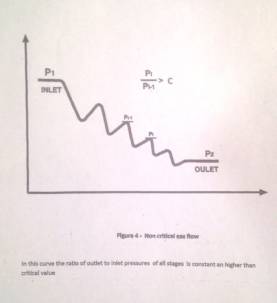
-Sonic conditions, associated to compressible fluids, appear when the ratio P2/P1 reaches a critical value (which depends on the gas specific heats ratio).
Both cavitation and sonic, are associated with partially or fully choked flow conditions.
The objective of the different multistage valve designs is twofold.
-to suppress liquid cavitation, by keeping the liquid static pressure in the vena contracta of every stage above the vapor pressure,
-to maintain the pressure ratio above the gas critical ratio value (Regime I Subsonic Flow as defined by ISA-75.17 (IEC 534-8-3).
Inside multistaged control valves a critical large pressure drop is distributed among several, smaller non critical pressure drops.
The purpose of this article is to calculate the minimum number of steps necessary to achieve the above, the distribution of the pressure, or pressure profile and the stage Cv values.
-A number of stages lower than calculated will give cavitation /sonic conditions at some point
-The pressure profile requiring the minimum number of steps has decreasing pressure drop values, increasing Cv values, from first to last stage.
As a summary, the solutions recommended here assure the suppression of critical conditions with the minimum number of stages
We will consider only those multistage valve designs that have:
– a constant number (two or more) of pressure reducing stages
– geometrical similarity and same Cv characteristic of the stages
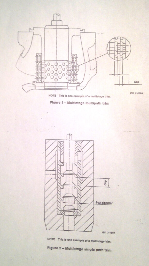
Examples are valves with concentric cages (Fig. 1) Multistage-multipath trim, or with a multiple plug (Fig. 2) Multistage-single path trim designs, as shown on IEC 60543-2-5.
Not included are valve trims with a variable number of stages, or combinations of valve and fixed Cv restrictions (drilled plates).

DESIGN RULES
On the basis of the above considerations, the following rules have been followed.
- There must not be critical conditions, choked flow (cavitating, sonic) at any stage of the pressure profile. Calculations will be based on tests or generally accepted individual stage (single drilled cage or parabolic plug) features, FL or xT.
As an example FL = 0,9 or xT = 0,68 for a single drilled cage with flow under the seat.
- To minimize the number of stages, the pressure drop at every stage will be the maximum compatible with 1. The first stage will take the maximum pressure drop as it has the highest inlet pressure. Following stages will absorb pressure drops with values decreasing with their inlet pressure.
- A safety factor should be added to take into account that incipient damage appears at lower pressure drop value than choked condition. This article offers the safety margin in all cases. Whether this margin is sufficient or not to avoid the incipient damage level is up to the manufacturers who, by experience or tests, will determine the safety factor values if needed.
EQUATIONS
The following symbols and signs have been used in the equations which determine the required number of stages, safety margin, steps pressure and Cv values.
SIGNS
(^) power, (*) multiplication, (/) division
SYMBOLS, in addition to symbols used in IEC 60534-2-5
-Nc and n, for calculated and selected number of stages respectively
-Cg for critical pressure ratio P2/P1, sonic condition, resulting from the gas specific heat values
-Cc and C, for calculated and selected critical pressure ratio values respectively
-R^2 for percentage of pressure recovered R^2 = 1-FL^2
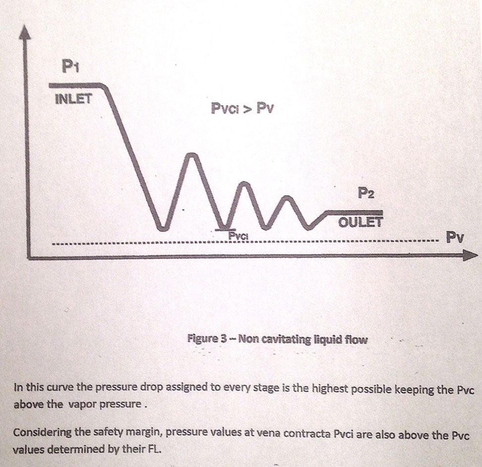
EQUATIONS FOR LIQUID SERVICE (See Fig 3)
STAGES NUMBER
Based on criteria 1 and 2, the minimum number of stages is given by the formula
Nc = (( log (P2 – Pv) – log (P1 – Pv) )) / log (R^2) (1)
where R^2 = 1–FL^2.
(take next integer n > Nc)
SAFETY MARGIN
The pressure in the vena contracta is
Pvc = (P2 –P1* R^2n)/ (1-R^2n) (2)
(this value is common to all steps)
and the safety margin is Pvc / Pv
PRESSURE PROFILE
The steps pressure drops are
(P1 – P21)= (P1 – Pvc)* FL^2 (3)
…………………
(Pi – Pi+1) = R^2(n-i) *(P1 – Pvc) *FL^2
VALVE AND STEP Cv VALUES
Calculate the combined Cv based on non choked conditions
Cv = Q / (P1- P2) ^1/2 (4)
The stages values are
Cv1 = Cv*(( (1 – R^2n)^(1/2) )) / FL
Cv2 = Cv1/R
…………………….
Cvi = Cv1/R^(i – 1)

EXAMPLE OF MULTISTAGE CALCULATIONS, GAS SERVICE
Take an 8” valve in compressor discharge service
Air temperature is 20ºC, 68º F, air critical P2/P1 ratio 0,528
Intet pressure P1 = 1090 psia and P2 = 145 psia (x = 0,867).
Flow rate 120.800 m3/hour, or 3.420.000 ft3/hour
Number of stages (taking C = 0,6) Nc = 3,8 and we take n = 4 Eq. 5
Actual ratio (P2/P1) C = 0,135^(1/4) = 0,605
Safety margin (0,605/0,528 = 1,14) 14% Eq. 6
Step pressure values 657, 397, 238 and 145 psia Eq. 7
Combined valve Cv value 108,2
Step Cv values 134,2 223,7 371 and 620 Eq. 8
REFERENCES
ISA 75/IEC 60534-2-1 (2002) Industrial Process Control Valves Part 2-1: Flow Capacity – Sizing equations for fluid flow under installed conditions.
IEC 60534-2-5) Industrial Process Control Valves Part 2-5: Flow Capacity – Sizing equations for fluid flow through multistage control valves with interstage recovery.